Earth Electrode Resistance
Earthing of electrical systems is essential for the correct functioning and the protecting of life and equipment in the event of faults. The earth electrode (connection of the earthing system to the ground) is an essential part of any system.
The estimation of electrode resistance and functioning during the design stage ensures workable solutions are proposed, enhances the operation and potentially reduces the cost of any installation.
General Calculation of Electrode Resistance
Theoretical Example
Sphere of radius r, fully surrounded:


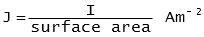
Method - assume a current I, is injected into an electrode then at some point distant from the electrode, the current density is:
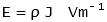
If the resistivity of the ground is r, the electric field is:
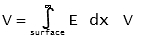
By integrating the electric field from the surface of the electrode to infinity, the voltage of the electrode is:
Apparent resistance Rg, can now be found from:

Resistance and Distance from an Electrode

Resistance Contribution v's Distance Around an earth electrode the resistance of the soil is the sum of series resistances of virtual shells of earth propagating outward from the electrode. Shells nearest to the electrode have the smallest surface area and hence the largest resistance.
The figure illustrates the contribution of the earth to the total resistance of the electrode at increasing distances from the surface of the electrode. As can be seen from the figure, 67% of the total resistance is accounted for at a distance of 0.3 M from the electrode.
In high resistivity locations, decreasing the resistivity in the area close to the electrode by use of ground enhancing materials (chemical treatment or the use of concrete) will improve the effectiveness of the earth system.
Resistance to Ground (Earth)
The following formula (source: IEEE Std.142:1991) enable the resistance to ground to be calculated.
 | Hemisphere, radius a |  |
 | One ground rod, length L, radius a | 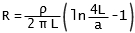 |
 | Two ground rods, s > L, spacing s | 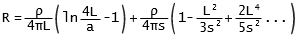 |
 | Two ground rods, S < L, spacing s |  |
 | Buried horizontal wire, length 2L, depth s/2 | 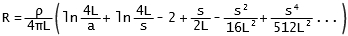 |
 | Right angle turn of wire, length of arm L, depth s/2 |  |
 | Three point star, length of arm K, depth s/2 |  |
 | Four point star, length of arm L, depth s/2 |  |
 | Six point star, length of arm L, depth s/2 |  |
 | Eight point star, length of arm L, depth s/2 |  |
 | Ring of wire, diameter of ring D, diameter of wire d, depth s/2 | 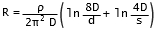 |
 | Buried horizontal strip, length 2L, section a by b, depth s/2, B < a/8 |  |
 | Buried horizontal round plate, radius a, depth s/2 | 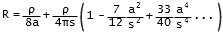 |
| | Buried vertical round plate, radius a, depth s/2 | 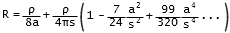 |
Where:
R - resistance in Ω
ρ - resistivity in Ω.cm
d - distances - in cm
Multiple Ground Rods
Spacing Factor
| No.Rods | F | | 2 | 1.16 | | 3 | 1.29 | | 4 | 1.36 | | 8 | 1.68 | | 12 | 1.80 | | 16 | 1.92 | | 20 | 2.00 | | 24 | 2.16 |
|
Spaced several rod lengths apart: 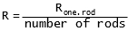
Spaced one rod length apart: |
Ground Enhancing Materials
Ground enhancing materials (GEM) is a technique where the ground immediately surrounding an earth electrode is replaced with a low resistance material. The intent is to reduce the earth electrode resistivity. Use of GEM would be in areas where the ground resistivity is very high and problems arise in trying to achieve the required electrode resistance.
Calculation of Resistance
The resistance, R, expressed in ohms , of a vertical electrode surrounded by an infill of material
is given approximately by the following equation[2]:

Given:
ρ - resistivity of soil (Ω.m)
ρc - resistivity of infill material (Ω·m)
d - diameter of electrode (m)
D - diameter of infill (m)
L - length of electrode (m)
Issues and Concerns
GEM treatment may not be permanent and should be check regularly. This is particularly true of chemical treatment which may leach away into the surrounding soil over time resulting in the earth electrode resistance increasing to unacceptable levels. Some GEM treatments may also have corrosive effects on the earth electrode or other negative environmental consequences.
References
- [1] IEE Std. 142-1991, Grounding of Industrial and Commercial Power Systems, Institute of Electrical and Electronic Engineers
- [2] BS 7430:1998, Code of Practice for Earthing, British Standards Institute